Next: Xwindow Interface Up: Manipulators Previous: Rotational Joint Contents Index
A model of a manipulator is described by manipulator. defmanipulator macro below creates an instance of manipulator.
 (defmanipulator manipulator-name

  :class   manipulator-class

:base 		 base-joint

:joints 		  list-of-all-joints

:hand 		 handjoint

:left-finger 		 left-finger

:right-finger 		 right-finger

:handcoords 		 trans-from-hand-to-armsolcoords

:toolcoords 		 trans-from-armsolcoords-to-toolcoords

:open-direction 		 finger-open-direction

:right-handed 		 righty-or-lefty

)
  :super   body

  :slots 		 (axis offset high-limit low-limit)
  :super   cascaded-coords

  :slots 		 (base baseinverse joint


angles right-handed hand handcoords right-finger left-finger


openvec max-span toolcoords toolinverse armsolcoords


toolinverse armsocoords approach grasp affix)
![\begin{emtabbing}
{\bf :create}
\it\=\&rest args \\lq [method]\\
\>\&key \=((:na...
...)
((:lefty lft) t)
((:act a) nil)\\
\>\&allow-other-keys
\rm
\end{emtabbing}](manual-img93.png)
manipulator manages the linkage of the coords of base, joints(J1...J6), handcoords, toolcoords. manipulator has cascaded-coords as super-class. manipulator is connected with base which is cascaded-coords (or subclasses of body). manipulator manages the transformation from the base frame to the toolcoords. Messages sent to manipulator (i.e. :translate, :locate, :rotate, :orient, :transform etc.) effect the end effector of the manipulator. If WRT parameter is set one of keywords (i.e. :local, :parent, :world or an instance of coordinates) in this message, the end-effector moves with respect to the WRT parameter. In the next program eta3 is a instance of manipulator.
กก(send eta3 :translate #f(0 0 -100))        ;put back the end-effector by 10cm
กก(send eta3 :translate #f(0 0 -100) :world) ;move down the end-effector by 10cm
กก(send eta3 :translate #f(0 0 -100)
             (manipulator-base eta3))  ;move down the end-effector with respect
                                       ;to the coords of the base by 10cm
When manipulator receives these messages, it calculates the arm solution and 6 joint angles are determined. Generally, more solutions than one exist. In that case, one appropriate solution is chosen of them according to the criteria (i.e. the distinction between right-handed and left-handed, and the consistency with current joint angles). If there is no solution for a given configuration or the calculated joint angles exceed its limits, manipulator does not move and it gives a warning.
Arm-solution method :armsol must be defined for respective manipulator classes which correspond to real manipulators. This method calculates the transformation between the base-coords and the hand-coords. Thus this allow us to put a manipulator wherever with respect to the world-coords. The arm solution is independent of the base, toolcoords.
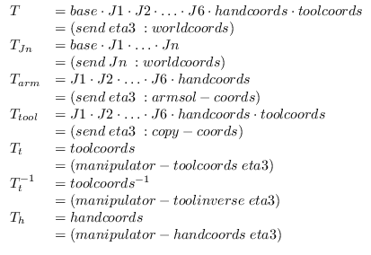
Fig. 15 shows the relation between coordinate systems
(base, J1, J2,..., handcoords and toolcoords). ![]() and other
transformations are calculated as follows.
and other
transformations are calculated as follows.

where ![]() is the transformation between the world-coords and the toolcoords.
is the transformation between the world-coords and the toolcoords.
Each joint has a geometric model represented by Breps (Boundary Representation). The coordinates of the vertices and the equations of the planes are not always current ones. Messages sent to manipulator for translation or rotation only update the coordinate systems, these do not update the coordinates of the vertices. This is why we can reduce the calculation time when translation or rotation occurs successively. If :worldcoords message is sent to manipulator, it updates the data such as the coordinates of the vertices.
Mainly toolcoords are used for specify the motion of a manipulator in this manipulator. There is a method (:config) for specifying the configuration of the manipulator by joint angles. The arguments are a float-vector whose elements are 6.
(send eta3 :config (float-vector pi/2 pi/2 0 1 0 1))
:config rotates joints of the manipulator if the joint angles are in the limit. As a result, the coordinates which manipulator manages and the current toolcoords which given joint angles determines become inconsistent. :set-coords message must be sent if you need consistency. :set-coords calculates a forward kinematic solution and calculates the arm solution using the forward kinematic solution.
Example: create the manipulator model (ETA3) and draw this on a Xwindow system.
;EusLisp 7.27 with Xlib created on Thu Sep 17 14:33:30 1992
(load "view.l")                                ;open a window
(load "/usr/local/eus/robot/eta3/eta3build.l") ;create the model of ETA3
(send *viewing* :look #f(2000 2000 2000))      ;change the viewpoint
(send-all (eta3arm-components eta3) :color 1)  ;change the color of lines
(send eta3 :config (float-vector 0 (/ -Pi 4.0) Pi/2 0 (/ -Pi 4.0) 0 ))
					       ;set joint angles of ETA3
(send eta3 :set-coords)                        ;refer to the above explanation
(draw eta3)                                    ;draw ETA3
k-okada 2013-05-21